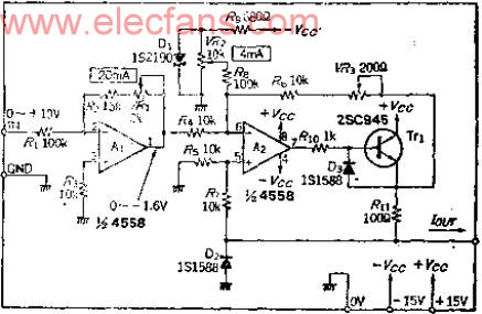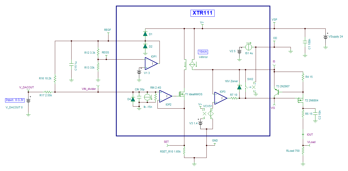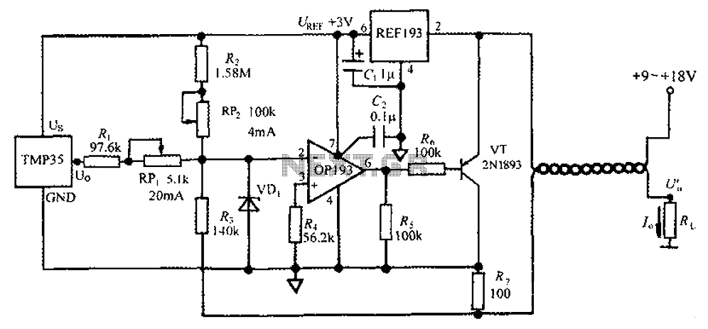

This 4-20mA current loop technology is used in temperature sensors, pressure sensors, current sensors, distance sensors, magnetic field sensors and much more. Despite being one of the oldest industry standards a lot of users have difficulty understanding the working of this technology. This 4-20mA current loop interface is also known as 2 wire interface technology. Follow this simple guide and we will show you a few tips to make it fast and easy.Ĥ-20mA current loop is most common and widely used communication method in an industrial environment. Secured guest checkout is available.Reading 4-20mA current loop sensors using Arduino is much easier than you might think.Support various types of bank card payment.Paypal online payment secured if you have a Paypal account. Credit card payment through Paypal secured if Paypal service is available in your country. Credit Card, Visa Card, Master Card, etc online payment. Shipped by DHL, EMS or Post Registered Air Mail Parcel, etc, or based on customer requirements. Select the parameters and quantity -> then click Button" Add to cart" -> then Button "View cart"->go next step accordingly.
#4 20ma to 0 10v converter circuit diagram manual

4-20mA(0-20mA)/0-5V and other analog signals isolation and conversion.Analog signal GND interference inhibition and data isolated acquisition.Industrial site signal isolation and long-distance transmission without distortion.DC current/voltage signal isolation and conversion, 1-input 1-output.Standard 35mm rail-mounted package, flame-retardant shell.

#4 20ma to 0 10v converter circuit diagram full

The signal converter is mainly applied in 2-wire or 3-wire 4-20mA signal to standard 4-20mA, 0-5v, 0-10v, etc. Inside the signal converter module, there are analog signal isolation amplifier IC, multi-isolation DC/DC conversion modules, etc., these high efficiency components used to process signal in high accuracy and high efficiency. HIC IAD DC Current Voltage 4-20mA to 0-5V 0-10V Converter is a kind of magneto-electric isolation amplifier which can convert and amplify industrial site signals in linearity.


 0 kommentar(er)
